CellStick
Getting Started with the CellStick
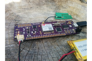
The board comes pre-flashed with a test program. All you have to do is the following to run an out-of-box diagnostic:
- Connect a cellular antenna to the uFL connector.
- Connect a 3.7V LiPo battery to the JST connector.
- Insert a SIM in the tray on the underside.
- Connect a micro USB cable to the device.
- The unit will now power on (Green LED). Hold down the tactile switch for a few seconds, and the blue netstat light should start flashing to indicate the system power up.
- Launch the Arduino IDE, and a serial monitor at 115200 baud to see the CellStick diagnostic menu print out.
Getting Started setup
There-after, if you would like to write your own code on the CellStick, the Arduino IDE with UNO as the board type will do. The Arduino library committed to GitHub at github.com/tinkeringtech/Cellstick is the library used with the board.
The CellStick comes pre-loaded with the Arduino bootloader on the ATMEGA-32u.
CellStick pin information
JST 2-pin – Battery input connector. It works with a Lipoly battery but since the charge rate is 500mA we suggest a 500mAH or 1200mAH battery. A battery must be connected to this connector in order to power the SIM800H. The purpose of this additional power source is to supply enough current to the SIM800H when functioning. The onboard charging circuitry will keep the LiPo battery connected to the JST charged at all times via the USB port or a battery connected to VBAT.
VBAT – External power supply when the CellStick is not being powered through the micro USB connector. The VBAT can be anything up to 16V.
PK – This pin is tied to the tactile switch and controls the power up of the SIM800H module. Tie it to ground permanently to power on the module when the board is powered.
CellStick SIM800H test point information
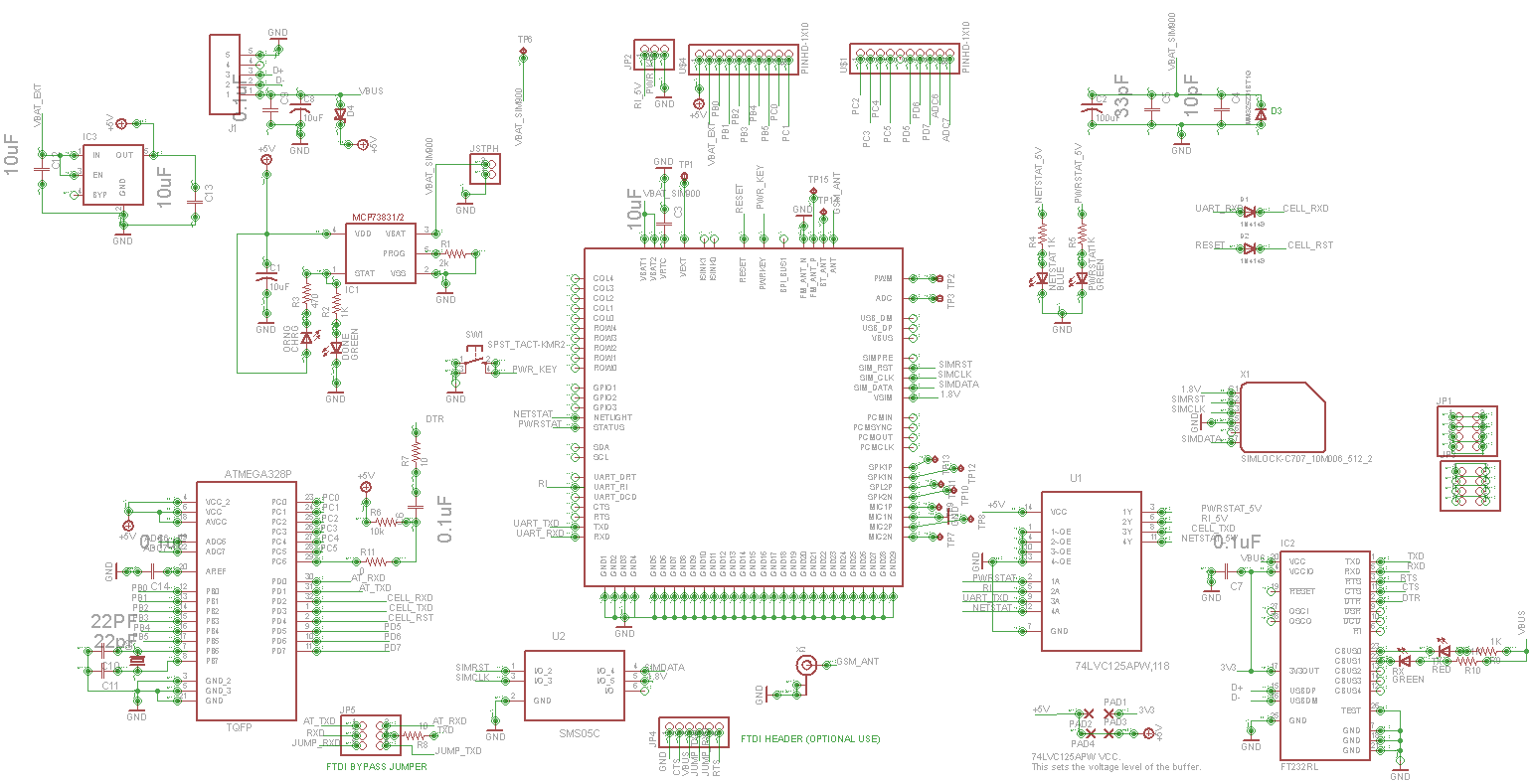
All the pins of the SIM800H module were purposely broken out on the PCB to enable the user to add other functionality if needed. This can include adding voice, bluetooth or FM radio functionality. These additional features have not been tested but should work with the relevant circuitry. Please refer to SIMcom's documentation for more details.
- TP1 – Output voltage 2.8V
- TP2 – PWM
- TP3 – ADC
- TP6 – VBAT
- TP7 – MIC2N
- TP8 – MIC2P
- TP9 – MIC1P
- TP10 – SPK2N
- TP11 – SPL2P
- TP12 – SPK1N
- TP13 – SPK1P
- TP14 – BT_ANT
- TP15 – FM_ANT_P
For more details on each of the pins, please refer to the SIM800H hardware userguide.
CellStick Schematic